Motor and DRV2605 Report
ERM

LRA

Usage
Driver -DRV2605L — Datasheet
- Supply voltage 2 ~ 5.2 V
- PWM input frequency 10~250 kHz
- LRA Frequency Range 125 ~ 300 Hz
API
begin()
Begin I2C communication to the microcontroller
useERM()
Use ERM (Eccentric Rotating Mass) mode.
drv.begin();
drv.useERM();
useLRA()
Use LRA (Linear Resonance Actuator) mode
drv.begin();
drv.useLRA();
selectLibrary(lib)
lib: 0 = empty, 1–5 ERM Library. 6 LRA Library
setWaveform(slot, w)
Playback starts at slot 0 and continues through to slot 7, stopping if it encounters a value of 0.
slot: 0–7
w: 0–123. The waveform sequence value refers to an index in the ROM library.
e.g. setWaveform(slot, 0); //stop the vibration
go()
I2C triggers by sending the ‘go’ command. Trigger command
stop()
Stop playback.
setMode()
DRV2605_MODE_INTTRIG 0x00 ///< Internal trigger mode DRV2605_MODE_EXTTRIGEDGE 0x01 ///< External edge trigger mode DRV2605_MODE_EXTTRIGLVL 0x02 ///< External level trigger mode DRV2605_MODE_PWMANALOG 0x03 ///< PWM/Analog input mode DRV2605_MODE_AUDIOVIBE 0x04 ///< Audio-to-vibe mode DRV2605_MODE_REALTIME 0x05 ///< Real-time playback (RTP) mode DRV2605_MODE_DIAGNOS 0x06 ///< Diagnostics mode DRV2605_MODE_AUTOCAL 0x07 ///< Auto calibration mode
setRealtimeValue(rtp)
Set the realtime value when in RTP mode. Use to directly drive the haptic motor.
rtp: 8-bit value e.g. 0xA0
writeRegister8()
Write an 8-bit register.
readRegister8()
Read an 8-bit register.
Feature
- Support ERM and LRA actuators, using
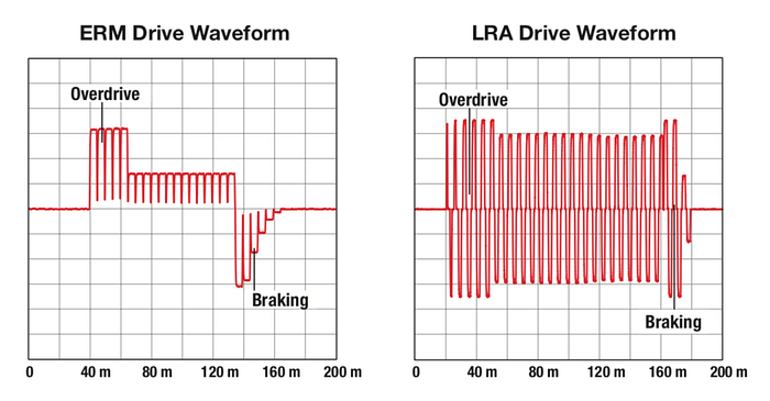
useERM()anduseLRAto switch the mode. - Smart-Loop Architecture, allows the motor have a faster start time by using Automatic Overdrive. And also have quicker stopping with active braking.
3. Automatic Level Calibration, which provide consistent feel across actuators
4. Actuactor Diagnostics, using setMode(DRV2605_MODE_DIAGNOS)could check the status of the actuator easily
5. Auto-Resonance
An LRA actuator will produce vibration when exercised at or near its resonance frequency. When the driving frequency is closer to the resonance frequency, the stronger vibration that LRA provides.
The LRA has a narrow operating bandwidth centered around the resonant frequency and its resonant frequency will vary due to numerous external factors including mounting position and acceleration (see graph to the left).
Auto-resonance tracking provides consistent and strong vibration across all actuators.
6. This driver also allow convert extent Audio single input and convert into virbration. On the other hand, this driver could generate auido by transfor audio single into virbration.
Application
- Generate Vibration
- Create tactile texture.
- Mobile Phones, Tablets, Watches and Wearable Technology
- Remote Controls, Mice, and Peripheral Devices
- Touch-Enabled Devices
- Industrial Human-Machine Interfaces
Example Description
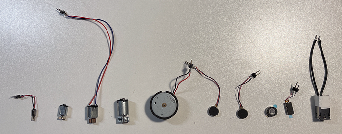
I plan to build a low-cost construction kit to test different vibration textures and vibration feeling with different sizes and kinds of vibration motors.
Component includes:
Motors:
FRS Strip: Test Swipe on the surface.
FRS Circle: Test the touch on the surface.
DRV2605L.
3.5mm Audio Input Jack: Input extern signal to the board.
And a 3D printing pad that can mount the circuit board and some motors on it.